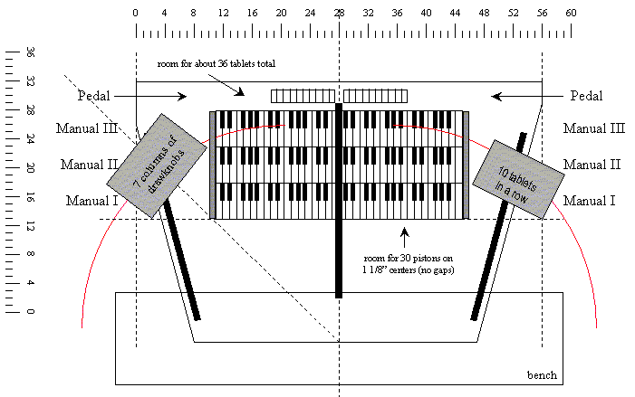
The drawing below shows a plan, or top view. Notice that it is the pedalboard which dictates the overall width of the console. The drawing shows two possible configurations of stop controls, one for drawknobs and one for tilting tablets. The sizes for both are based on actual dimensions; the tilting tablets would be mounted on a slanted surface.

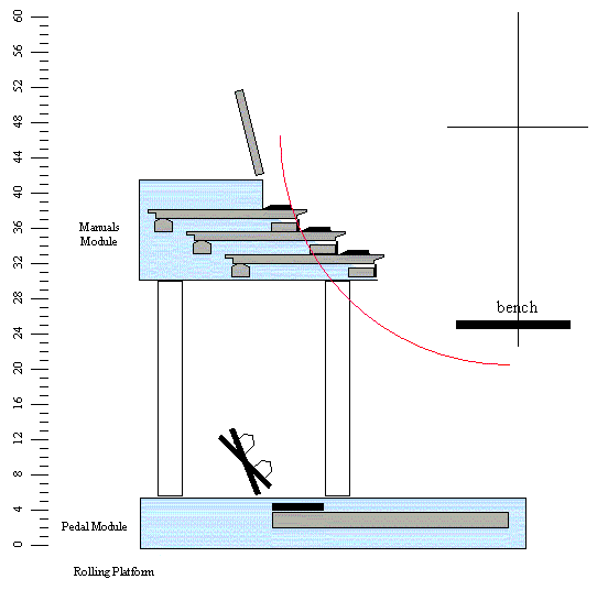
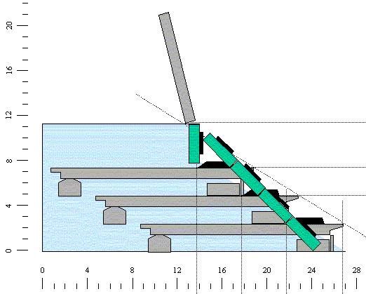
The drawing below shows a side elevation. Notice that the overall depth is a function of both the manuals and the pedalboad. The two main assemblies are joined by four pedestals, an open design which allows the performer's feet to be seen from any angle. Expression pedals are shown at their angular extremes, along with two rows of toe pistons (which look like they're mounted on the expression pedals, but really aren't). In theory, the two main assemblies could slide horizontally front-to-back with respect to each other, resulting in an even more compact form for storage, but this is not an idea I have pursued.
The drawing below shows a front elevation. The row of toe pistons shows how many will fit in a row; I would use two rows. While the left stop jamp contains three rows of tilting tablets, for my purposes I would need four, as indicated at the right (not in its correct position).
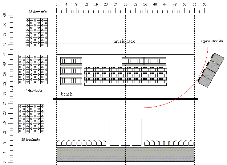
The drawing below shows a more accurate relationship between the three manuals and the four rows of tilting tablets.
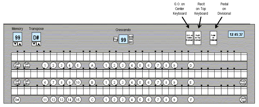
The drawing below shows a front elevation detail of the manuals and pistons. The 3-row group of pistons on the left numbered 1-15 are generals; the three groups numbered 1-9 are divisionals.
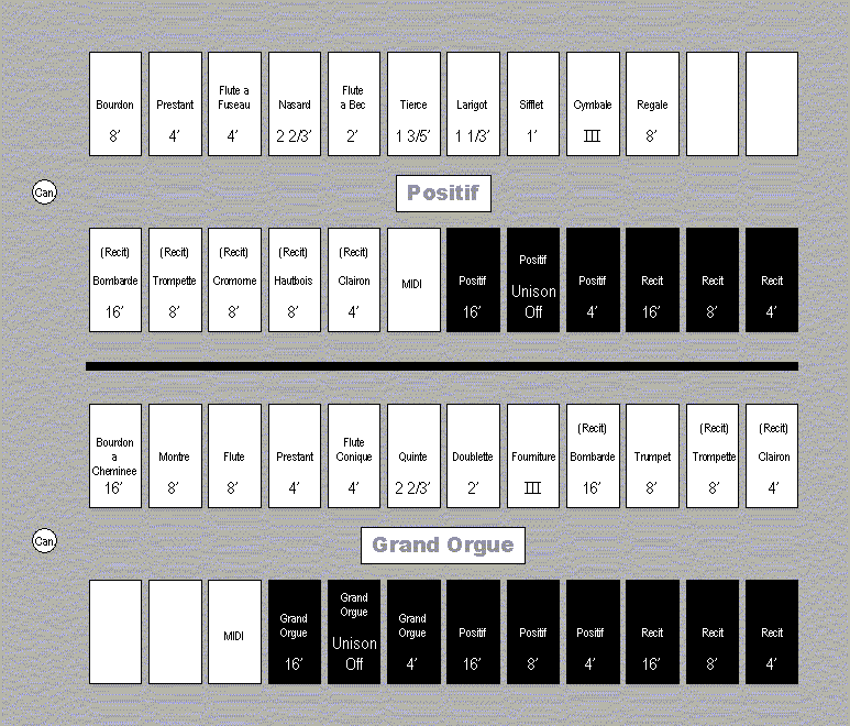
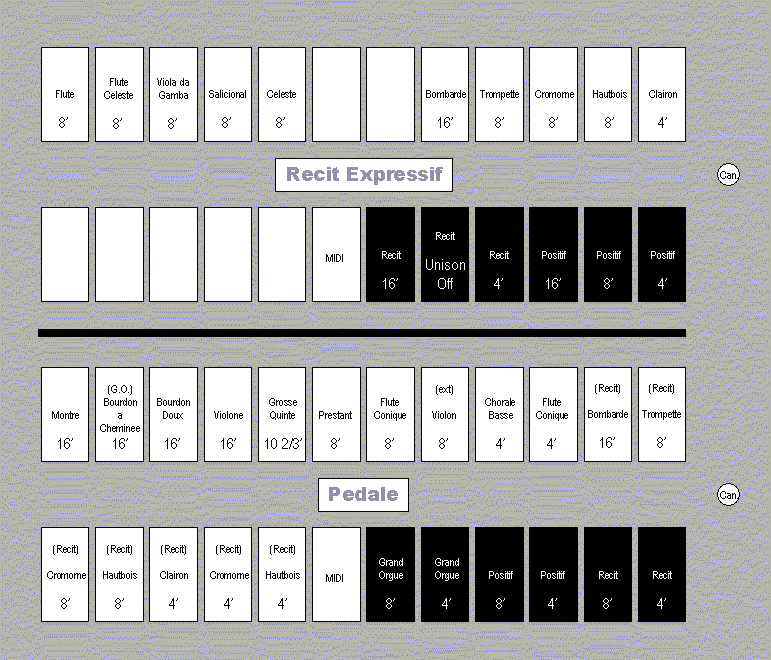
The drawing below shows the left stop jamb. I've used all available space for tilting tablets, with a number left blank for future expansion. In a future refinement of this design, I'd probably assign some of the second row to the pedal, to give it some extra tablets. The 'Can' buttons are divisional cancels.
The drawing below shows the right stop jamb.
